
Explore the Library
RESOURCE LIBRARY EDUCATION
Support Series
You can count on outstanding support from Ideate Software. To help all customers get the answers to workflow questions quickly, we often post questions asked by customers and our support teams' responses.

SUPPORT - ARTICLE | Ideate Software Installer is a one-click tool to help deploy Ideate Software throughout an organization. The installer package includes all the MSI files for the most recent versions of all our desktop solutions.
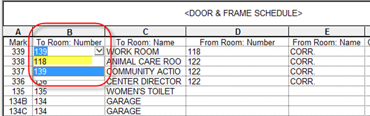
SUPPORT - ARTICLE | Door elements exist between two rooms. Often, the numbering goal is to associate the door number with a particular room number, so listing both room numbers is not always useful.

TRAINING - VIDEO | Ready to kick off your day without the wait for Revit files to open? With Ideate Automation, your models can be scheduled to be open and ready for you. From long file opening times to weekly PDF exports, let us make your job easier.
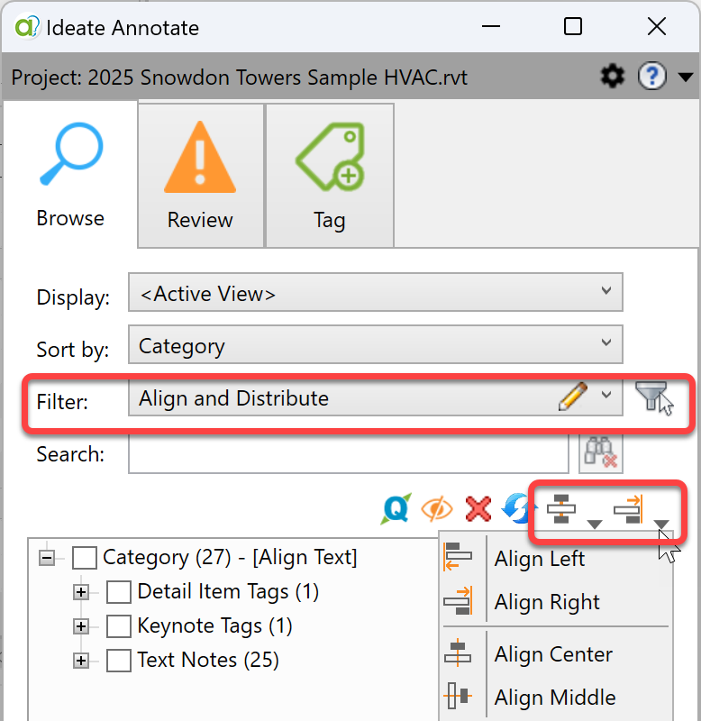
NEWS - ARTICLE | Welcome to the world, Revit 2025! For those who may have missed it, the newest version of Revit slipped into our subscription centers quietly in early April. You can learn about Autodesk’s version of What’s New in 2025 online, but if you ask me, the best new feature is the ability to now align text and tags.
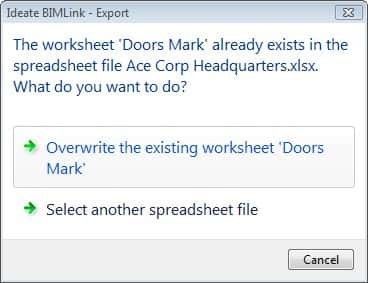
SUPPORT - ARTICLE | When users want to leverage an existing Excel file instead of creating a new one, they have two options to export Revit schedules to Excel.
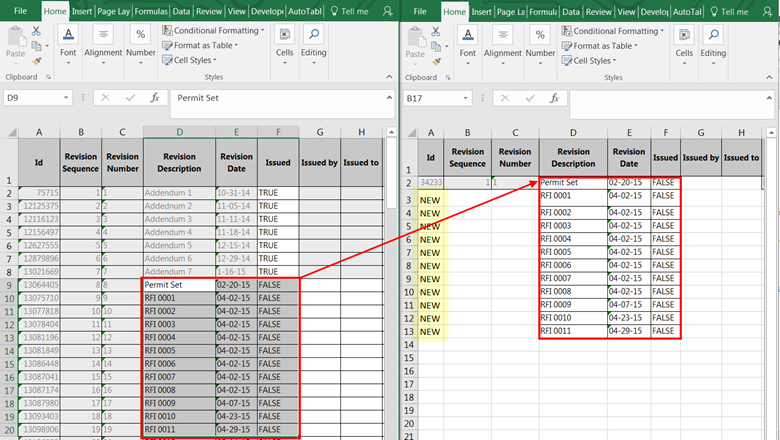
SUPPORT - ARTICLE | You can use Ideate BIMLink to easily create new sequence revisions in Revit. Here are instructions.
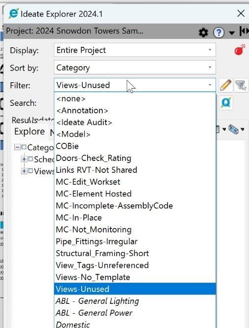
SUPPORT - ARTICLE | Recently a customer asked if we provide a tool that can report on whether schedules and legends are placed/not placed on sheets. In case you’ve wondered that too, here’s our response.
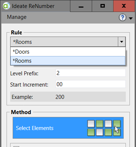
SUPPORT - ARTICLE | The numbering of Rooms or Spaces is often the most subjective of numbering tasks. Here are two ways to do it using Ideate ReNumber.
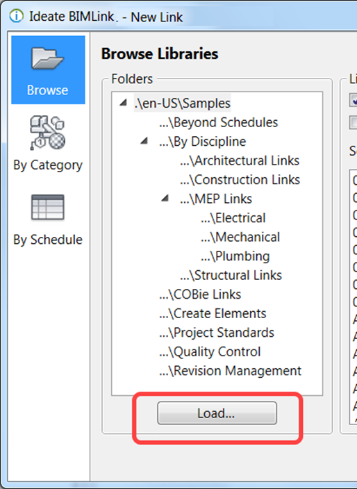
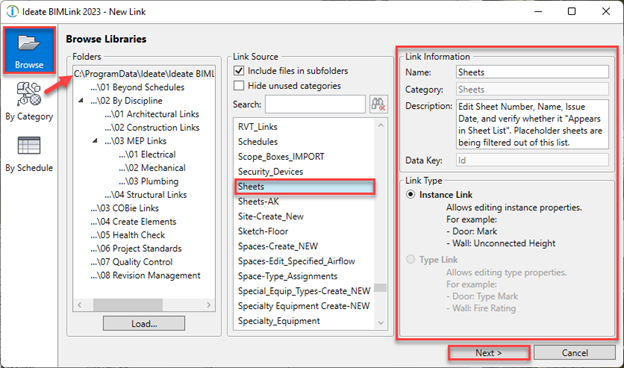
SUPPORT - ARTICLE | When a link definition has been created in another project and saved to disk as a .link file, it can be then loaded back into a new project.
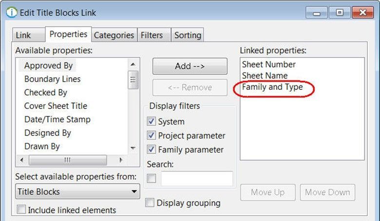
SUPPORT - ARTICLE | Type swapping can be used to edit the kind of title block assigned to each sheet in the Revit project. This is easily accomplished with Ideate BIMLink.
SUPPORT - ARTICLE | Door elements exist between two rooms. Often, the numbering goal is to associate the door number with a particular room number, so listing both room numbers is not always useful.
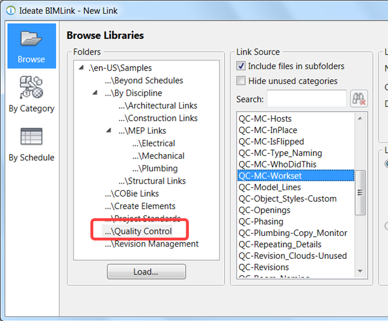
SUPPORT - ARTICLE | In the Quality Control folder you'll find a variety of tasks, such as checking the fire rating of the wall against the fire rating of the door, or in checking the elevation height of all devices.
SUPPORT - ARTICLE | The Revit interface has limitations in terms of editing large amount of data. Ideate BIMLink allows you to edit model data by exporting it to Excel and pushing it back into Revit.
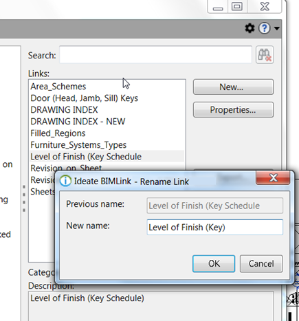
SUPPORT - ARTICLE | Link names are limited to 25 characters or less due to Excel worksheet name requirements.